Machine-Vision Fibre Alignment
Real-time microscope imaging and quantitative intensity analysis for locating the optical-fibre core, monitoring focus, and converting a manual alignment task into a repeatable measurement.
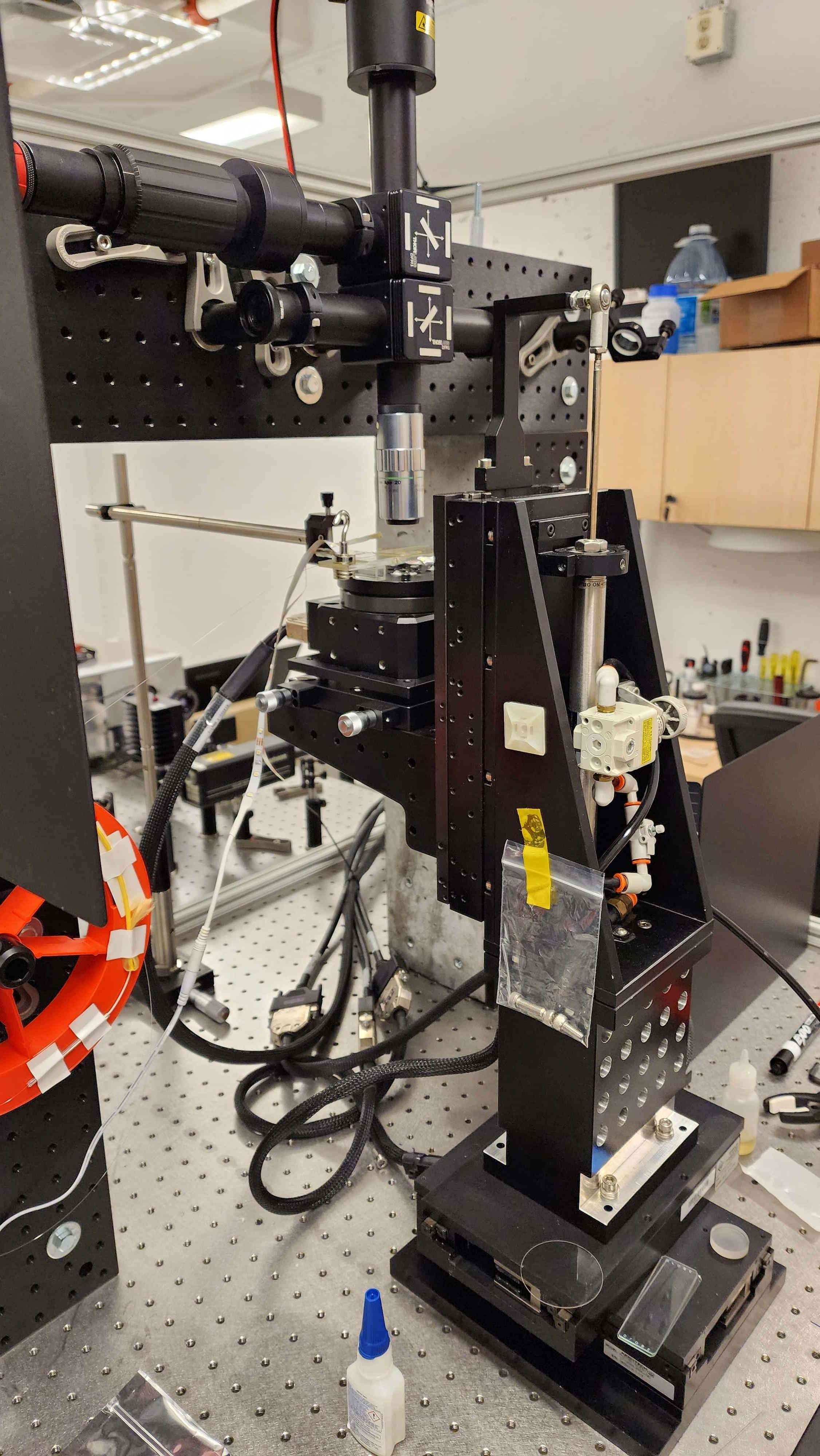
Make alignment visible, measurable, and automatable.
The usable target in fibre inscription is only a few micrometres across. The laser focus must be placed relative to the core, not merely the outer glass boundary, and that relationship must be maintained as the fibre translates and rotates.
A live camera view is helpful, but a quantitative image pipeline is more useful. By extracting intensity profiles, edges, centroids, symmetry, and focus metrics, the alignment can be recorded and reproduced rather than judged only by eye.
From camera frame to alignment coordinate.
The software captures live microscope frames, selects a region around the fibre, corrects or normalizes the image, and calculates transverse intensity profiles. Features associated with the cladding edges and core region can then be tracked as the stage moves.
- Acquire and display low-latency microscope video during setup and inscription.
- Compute horizontal and vertical intensity projections across a selected region.
- Estimate fibre centre, core position, apparent diameter, and focus quality.
- Overlay measurements and reference markers directly on the operator view.
- Record alignment metrics alongside fabrication parameters for later comparison.
Alignment error becomes device variation.
The coupling strength of a laser-written grating depends on the overlap between the induced refractive-index modification and the guided optical mode. A transverse displacement changes that overlap and can also increase cladding-mode coupling or asymmetric birefringence.
Quantitative alignment therefore improves more than convenience. It supports cleaner comparisons between inscription conditions, reduces sample-to-sample variation, and makes it possible to distinguish true process physics from geometric drift.
Toward closed-loop fabrication.
The next stage is to connect the measured image coordinates to calibrated stage coordinates. The system can then suggest or execute corrections, check fibre position during long scans, compensate for slow drift, and reject an inscription if the target leaves a defined tolerance window.
Combined with automated spectral analysis, this creates the foundation for a fabrication loop that measures both the geometry before writing and the optical response afterwards.